Tuesday, November 29, 2011

More About the Motor: Wiring and Batteries

Our batteries are the fuel that make our motor go. Richard did a lot of research, we thought about safety, efficiency and cost. In the end we decided on premium AGM (Absorbed Glass Mat) batteries, an affordable compromise between flooded lead acid batteries (which would need to be vented outside the boat and require maintenance) and lithium (light, but expensive).

Our motor runs on 48 volts. We decided that two banks of batteries wired into 48 volt packs would allow us to find the best balance of space and weight. This meant that we had eight batteries to distribute in the way we thought would benefit us most. And that would be to keep them low and close to or in the middle of the boat.


We distributed them as follows:
  • Two batteries in the compartment below the floor boards that is closest to the motor.
  • Two batteries in the compartment forward of that (which leaves half of that compartment for other storage).
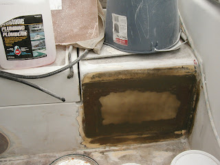
  • Two in the bottom of the old icebox (Richard cut away part of the old icebox floor and part of the wall so that the batteries would sit close to the center of the boat and low down).
  • One under the sink (Richard cut part of the liner so that it would be as low as possible, close to the center of the boat).
  • One in the 'wet locker' by the galley.

This did mean giving up some storage space, and having to divide the large compartment below the floorboards into two. In the old icebox and the wet locker the batteries will be covered to create a shelf in one and a new bottom in the other.

For our charging system we chose to use four 24 volt Guest chargers. They charge each battery individually. They keep the batteries in balance by making sure that each one is charged as much as it needs, and using them avoids the distortions that can happen in charging each battery that happen when they are charged as a string.

We chose Guest because they are completely waterproof and available at a reasonable price. And in the electric boat forum Richard belongs to those that have them were pleased with and recommended them. The chargers can be hooked up to either shore power or to a generator.

The rest of our charging system uses solar panels, or the regeneration that is built in to the motor, and these are what we expect to rely on most of the time.

One of our friends, Uli Rentsch, is an electrical engineer. He helped us to develop our wiring diagram.
For the wiring we used the type of wire used in battery cables (#2). Richard worked out the wiring size using a chart that shows the voltage loss for different sizes of wire. This size wire means that losses would be minimal with the current we're going to run.

We used lugs to connect the wires to the battery terminals, and protected all the connections with marine grade heat shrink which has a sealant in it that is activated by heat.

One very important thing we learned: as we wired the two 48 volt packs we needed to make sure that the lengths of the wires between corresponding pairs of batteries in each bank were the same. That is, the length of the wire between batteries 1 and 2 in the first bank had to be the same as the length of the wire between batteries 1 and 2 in the second bank, and so on. Each bank has its own switch, so that we can operate either on one or the other, or on both when both switches are turned on.

Setting the switches up this way means that if necessary (if, say, there is a problem with one battery in one bank) we can isolate the banks from each other and still have 48 volts of power to run on.

Using both banks at the same time has the advantage of reducing the Peukert effect. This can be described this way: The more current you draw from a battery the less capacity it has, so that it provides power for a shorter time than it would if you drew less current from it. You could think of it this way: the greater draw actually reduces the real capacity of the battery - a 10 amp draw from a 100 amp battery allows the battery to operate as if it had 100 amps, but a 50 amp draw on the same battery would make it operate as an 80 amp battery.


Although the wiring diagram does not show it, there is main fuse that acts for both banks when both are switched on and providing power as one.


Rather than have a separate battery, we decided to run house loads through a converter which steps the 48 volt current down to 12 volts. Partly this means not having to carry and find space for one more battery - but it also means that our batteries will be used rather than sit idle, and this is better for them.

The actual weight of the electric motor plus batteries, wiring and chargers, etc, is about the same as the weight of an Atomic 4 engine and a full tank of gas.

Wednesday, November 9, 2011

Goodbye Diesel, Hello Electric

So - Why Electric?

Everyone has their own reason for choosing what kind of motor they want as the auxiliary in their sailboat. When we bought Into The Blue we were very happy to have a diesel engine, preferring to have diesel rather than gas on board.

Then, as happens, our old diesel began to feel and show its age. When it finally and indisputably declared its reluctance to continue to operate without expensive repairs (assuming we could find the parts), and emphasized that reluctance by filling the boat with diesel fumes, we decided it was time to investigate what kind of motor to replace it with. We had learned that while sailing without an engine is certainly possible it can also be uncomfortable, and we appreciate comfort. So - time to make a decision.

Richard undertook the research. We were interested in electric motors for a number of reasons. One was that we would no longer have to listen to the thump of a diesel motor, or smell the aroma of diesel fumes. Another was the hope that with solar power to replenish the batteries, and careful use of the motor, we would largely be free of the need to buy fuel. We do foresee buying a generator, but experience on the water this summer has been reassuring. Regeneration while sailing works well, and should work better in the future. We should not have to use a generator too much - so some fuel on board, but much less.

So far we are very happy with our motor, which we bought from Electric Yacht. And very happy with Electric Yacht, who answered all our questions (and still do). Other things that are really nice: the motor is very quiet, and super simple to drive.

Installing the New Motor

Of course, before we could put our new motor in we had to remove the diesel. The engine was small, which helped simplify the process. And then we made it smaller by removing it in bits and pieces. First Richard took all the accessories off (like the alternator and water pump). Then he took other bits off, such as the head and cylinder and the front crank pulley, taking the bits off the boat as he went along. After that he separated what was left of the engine from the transmission, and took them off the boat separately.

That left us with a diesel-stained engine compartment, so the first order of business was to clean the compartment up. Richard cleaned and sanded, then painted the compartment with gelcoat (tougher than paint). The difference was very pleasant to see.

Once the compartment was clean Richard decided to take advantage of the space and ease of access to the area behind the engine to do a few other jobs. He replaced the hose on the stuffing box, the cutless bearing and the stuffing box packing, and put new hoses on the cockpit drains.

And now that we did not need them any more he removed the old coolant hose and its through-hull and filled the hull where the through-hull had been. One less hole below the waterline.

Then it was time to put in new motor mounts. The mounts on the engine would fall between the original motor mounts, so Richard put 1/4 inch thick stainless steel bar across between and bolted them into those original motor mounts.

After careful measuring, he drilled the stainless steel to take the mounts that came with the new engine and bolted them into place.


The next step was exciting - actually putting the motor in place. The mounts that come with the motor can be put together in a variety of ways, which means that there is a lot of adjustment possible when you are putting the motor in. It took a little experimenting to decide which combination seemed best. Then it was time to hook it up to the shaft.

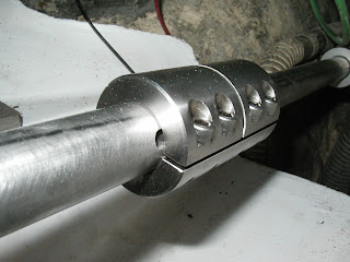
The motor comes with a special shaft coupling that helps align motor and shaft properly. Richard loosened all the bolts fastening the motor to its mounts. Loosening the bolts allows the motor a certain amount of adjustment as the shaft coupling does its work - the mounts on the motor are slotted to allow it to move backward and forward as you align it. The number of slots allow you to choose which height works best in your boat.


With everything in place, Richard tightened the shaft coupling, then tightened the mounting bolts on the engine in their slots. Then he used what we had to check that the shaft was straight: He bolted a coat hanger in place with the tip just touching the shaft, then rotated the shaft slowly while watching to see whether it moved toward or away from the coat hanger tip. All was as it should be. As the supplier had told us it would, the coupling aligned shaft and motor without problem.

The controls and instrumentation for the electric motor is considerably simpler than for the diesel. So we removed the old levers and instrumentation, and changed the areas where they had been.
The single lever for the electric motor we decided to install where the compass was (replacing the compass with one we can see from inside or outside). Changing the compass area and installing the batteries and wiring for the motor are processes we'll cover in subsequent posts.

Thursday, December 2, 2010

Deck repair: Foredeck

The largest area of the deck we needed to repair was the foredeck, where the windlass was (and will be again). We knew we would have to do something when we noticed that the deck was moving when we were pulling up the anchor - not a good sign. That movement plus the presence of some cracks indicated pretty clearly that the balsa core in the deck was probably wet and needed to be replaced.

The first thing we had to do was clear our deck - remove our windlass, and the hawse pipes that the anchor chains ran though - and remove the plate under the deck we had used to spread the load. The windlass needs repairs, so we would have had to take it off anyway and this was an opportunity to rethink how we had installed it in the first place. Among our concerns was finding a good way to strengthen the area and spread the loads of hauling up a reluctant anchor better. So we started the work on the deck - once again Richard did the fibreglass layups, and then I did the sanding and detailing.

The first thing that Richard did was cut the top layer of the deck where he knew repairs were needed. To start with he cut the top of the deck a little bit beyond the edge of all cracked areas. If he did not find dry balsa around the area that he had cut he cut back some more. We had hoped the top layer would come off in one piece, and keep it’s shape - but a combination of wet and dry balsa beneath it foiled that plan. The old deck continued to adhere to the small areas of dry balsa, so it had to be removed in bits and pieces. Once the top layer was off, he took out all the balsa out of the areas that were wet, and began the repair.


Since we wanted this area of the deck to be strong, he rebuilt the deck area without using a core. Instead he used two fibreglass layups, one to replace the core and one to replace the upper part of the deck.

He did the first layup on top of bottom layer of the deck, where the core would have been. First he put catalyzed resin on the top of the inside deck layer with a roller. On top of this he used 7 layers of mat and one layer of roving altogether - 2 layers of mat, one of roving, then the rest of the mat layers - to make a layer about a quarter inch thick. To do this he applied resin to each layer before the next one was put on and rolled the air out after all the layers were in place.


He also put three or four layers of mat and resin inside the boat, underneath the deck area where the windlass will be remounted, replacing the plate we had used to give the mounting area extra strength. Laying up above your head can be tricky - he put first layer up on a resin wet surface, but not as wet as if he were laying up on a surface that was below him - with small pieces the resin is sticky enough to keep them in place. If you are doing a larger area and have trouble getting the first piece to stick, you let it get tacky - but here the pieces were small enough not to create a problem - less than a foot square. Again, he put all the layers up and then rolled them out.

Once those were in place he began the top layer of the deck. To start with he taper ground all the edges of the remaining top deck layer, using a grinder. He took the taper about three inches out from the area being repaired.


As with the previous layer, he started with a layer of resin on the surface below. Then he laid up the top layer using mat and resin (no roving). He used four layers of mat, each one slightly bigger than the previous one, to compensate for the taper. He put the layers on, one after another, while they were still wet, and rolled out the bubbles after they were all on.


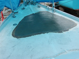
Then came my part of the work - the sanding. I used our trusty random orbital sander for most of the job, the small mouse sander to sneak into place that the bigger sander could not go, and a small hand sander for even tighter areas. After the first sanding, we filled the pinholes. Then I did more sanding, and some shaping to make sure that the deck contour looked right. Then there was more filling and more sanding. After that we rolled on the first layer of gelcoat - since it is more water resistant than just resin it provided some protection, and it was easier to see the contours of the deck with everything the same color.


That was sanded as well. Then, after another layer of gelcoat and more sanding, Richard rolled on the final layer of gelcoat. This time he added Air Dry, which is used to make this a hard, waterproof and sunlight resistant coating. Air Dry should only be added to the final coat, as new gelcoat will not stick to it unless it is sanded well.


We removed the smooth central ‘channel” that ran through the nonskid, and I reshaped the other channels around the area where necessary and sanded the whole foredeck so it was ready for painting with non-skid. Once that was done, we taped the nonskid area.


Finally we put on three coats of the non-skid paint we had chosen (Skid-No-More). This is picture of the first coat. Note to selves - we would have used less if we’d read the directions first!


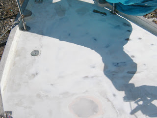
The final coat of non-skid is now on. The windlass is being repaired. We'll post the final picture when it's all done.

Tuesday, September 28, 2010

Replacing the Head Vent

We decided to change the head vent. As everyone who’s spent time aboard knows, this is a very important vent. It’s even more important than usual to us, since our composting head needs to vent continuously through it to work properly. Some Albergers on Chesapeake may remember the time the fan in that head quit working, and our desperate quest to replace it...

Why change it? The vent we had leaked gently at times, into both our head compartment and our head. It wasn’t easily accessible with the setup we had, nor could we close it when the weather turned nasty. And a close look suggested that the leaks might be because the dorade box the vent was sitting on wasn’t all that effective - so we decided that we would change to a closable vent without a dorade.

We had already changed the original cowl vent, and had a round vent (plastic, and unhappily destroyed when a heavy object hit it) sitting on our rectangular dorade box. So our first step was to remove the vent - and then the dorade box. We had already decided on a vent with a stainless steel cover that promised to move a lot of air, so the next part of our work was based on that purchase.

The vent would work best if it was sitting level (as level as anything ever sits on a sailboat), so creating a level surface for the vent to sit on was the next part of the project. Once we had cut the dorade off we were left with a hole around which to build the new base, and an area around it that needed to be repaired.

Since we had decided a round base would look nice and work well, Richard started by cutting circles of fiberglass mat. There were two considerations when cutting the mat:

* The base would be larger at the bottom than the top, and
* We had to build up one side (the out side) more than the other (the in side), due to the curve of the cabin roof.


- First, the size of the top circle was matched to the base of the vent we were installing.
- Then the bottom circles were cut larger than those for the top. To allow for the slope of the roof he cut progressively more off one side of the circle as he cut the lower circles. In other words, the bottom circle had the largest area removed and the longest straight line to be laid along the cabin, and the top circles were complete circles.

Since there was already an existing vent hole, Richard cut matching holes in the center of the circle for each piece of mat, and used the center hole to help center the layers of mat and resin as he worked. He also used the inside of the old vent to keep the hole open and even while he was working. Inside the head compartment he put tape over the hole to prevent resin dripping through.


Then he laid the circles up in a number of layers, centering them by matching the holes in the pieces of mat to the original vent hole. Each layer consisted of eight circular pieces and was laid up like this:

* First, polyester resin was rolled out on the surface to be covered.
* Then a layer of mat was put in place.
* The layer was saturated with resin, and the resin rolled out (pressed down into the mat) with a cheap 3 inch roller.
* Another 7 pieces of mat were put on the same way.
* After the eighth layer of mat, Richard used a steel roller on top to get rid of any air that might have been trapped during the lay up.


(When using the rollers, it’s important to press hard enough to get rid of any trapped air - you can see the air bubbles moving - but not so hard that the layers of mat move. This takes some practice.)

Eight pieces of mat create about a 1/4 in thick layer; Richard laid up 8 or 9 layers altogether, allowing each layer to cure before putting the next one on.

The first part of the process left us with a shape which was roughly the one we wanted. Refining the completed shape began when Richard put on the last layer of mat and resin. He mixed up ‘gunk’ (resin thickened with silica and talc) when he was preparing the resin for the last lay up, and spread the gunk on top of that layup to make a smooth, level top. On top of the gunk he put a piece of waxed plexiglass we happened to have, weighed down with a handy bit of former outboard bracket, and this left the hardened top surface nice and flat and smooth when we removed it.


( A note: we often work with things we happen to have at the time. You should know that waxed MDF board would have worked much better on the top of the vent base than plexi.)

Once everything had set, Richard mixed up and used more gunk to smooth off the sides of our new base. He applied the gunk with a flexible plastic spreader; by the time he was finished we had the basic shape.

After that I took over. I did a lot of sanding, to make the shape as smooth and symmetrical as I could. Then Richard gelcoated the whole base, and I went back to sanding - this coat of gelcoat helped me to see imperfections I would have missed otherwise and filled in some small areas. Another coat of gelcoat, brushed on thickly, was followed by more sanding. Then Richard used polyfair to fill in the remaining irregularities, and I sanded yet again.


Once the vent base was just about ready Richard used a rotozip to open up the hole in the middle to the size we needed for the new vent, and then cut away the thin layer of resin that had accumulated on top of the tape inside. With the hole was the right size and everything looked ready, another coat of gelcoat was applied, using a roller and covering the whole area that we had been working on. He also brushed gelcoat on the inside of the vent hole- that will be sanded when we start work on the inside of the head compartment.


A little sanding made the surface a little more even, and there will be more sanding before we put paint on the cabin and non-skid on the areas that need it, but for now we had gone far enough. So then we put the vent on!

Wednesday, September 1, 2010

The New Anchor Locker

By the time we came into Halifax last summer we knew that we would need to do something about our anchor stowage. When we set off on our adventures we had already had to rethink our original plan, which involved making slings of plastic mesh forward of the bulkhead separating the vee-berth from the bow. The mesh was not strong enough, so instead we devised two canvas slings to hold our anchor chains. They proved quite workable - the anchor chains did not rattle against anything except themselves, did not tangle and and were kept separated from each other. Overall, we had very little problem with them.

However, we knew that they would be a temporary solution. When we looked at them last fall the canvas was moldy and beginning to weaken. It was time to come up with a new and hopefully better solution.

When we were deciding what to do we had two considerations - to keep the anchor chains separated and safe, and to keep them - and their weight - low in the boat. With these thoughts in mind, Richard devised the anchor locker that now sits just under where the windlass will be installed.

This time the anchor locker is made of fibreglass, and sits low down in the bow, just in front of the bulkhead separating cabin from bow space. It is divided in two along the line of the bow, so that each chain will sit on one side of the barrier and against the hull.

To make it, Richard drew up a set of cardboard pattern pieces, first for the piece to go in the middle, then for a small piece to go toward the bow, then for the pieces that go from the bulkhead down to the hull, the rear wall of the compartment.

Then he made fibreglass panels, 1/4” thick ( 6 mm). He laid them up on a flat, waxed surface with the pattern pieces drawn on it, using mat and polyester resin, making them close to the size and shape of the pattern pieces, but a little larger. Then he used the pattern pieces to cut the finished pieces out, using a diamond cut blade on an angle grinder (he has become very proficient in the many uses of a grinder).

He put the middle piece of the locker in first (the one along the line of the bow), and fastened it in place with strips of fibreglass mat wet out with polyester resin.


Then he put the front piece in the same way.


Then the two pieces at the back.


Along the hull, up to the height of the middle divider, Richard added foam core plus a fibreglass matte layup, to deaden the sound somewhat and strengthen the hull where the chains may move around.


There are holes to allow the water to drain from the chains into the bilge, right in the middle of the boat, and holes at the front of the locker in case moisture needs to drain from there - also in the middle.

Once the whole anchor locker had been assembled, Richard rough sanded the whole thing to remove any sharp edges, and then finished it with brush gel coat (thicker than the spray) using two coats, sanded in between.


And there it is - our new anchor locker!

If you have any questions about what we did, or any comments, please click that comment button below and let us hear from you.

Monday, August 30, 2010

The Beginning...


Several things came together to let us know that it was time for a major refit. There was the time we saw the foredeck moving as we tried to work our anchor out of a nasty tangle. There was having to get towed off the rocks in Cape May in nasty weather - by our anchor chain. There was the reason we needed to be towed off - our engine had ceased to work. And then there was the fact that after our ocean voyages and other adventures Into The Blue was showing signs of wear and tear.

So we have resigned ourselves, as well as we can, to a land-based life, complete with work of the money-earning kind and an apartment with all the things that go with that - like rent and a minimum of furniture. And we asked around until we found a good place to put the boat on the hard, a place where we could pay our way and still have money to do the work we need to do and buy the equipment we need to buy to replace what we have worn out.

Needless to say, things do not always work out as planned - but we have been working away at some of the many jobs we decided needed to be done. We originally said we would work our way from the bow to the stern - and that’s how we started. But this is a boat, and one thing leads to another, and there is weather and temperature to consider...

For those who are interested in following us, we’ll try to divide the posts up into separate projects, rather than post chronologically.

Next post - our new anchor locker.